– Main attributes
– Part Number, manufacturer
– Description…
– Equipment connectivity
– Connectors, Nb pins, type, gauge
– Type, series
– Pin grouping
– Cable type (Shielded, Twisted, Coax…)
– Wire attributes (Color, gauge…)
– End fittings (Contacts…)
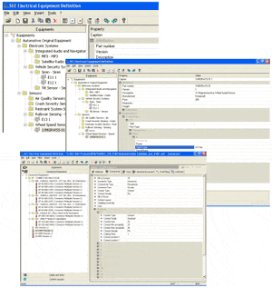
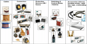
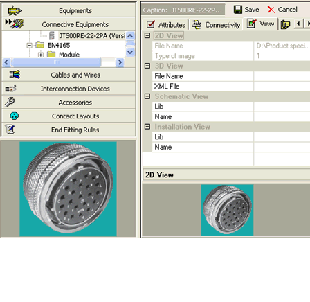
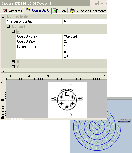
– Equipment Identification ( functional group, tag, .. )
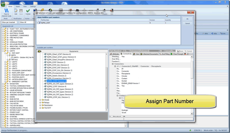
– Design Solution of Equipment devices (configuration)
– Equipment Part Number from See EED ( = specific supplier reference)
– Equipment connectivity
•Connectors
•Pins
• Definition of Equipment devices used in the final product.
• Management of variants (Configuration).
• By Integration Center (Panel/Rack)
• Access to Equipment List during Functional Design and Installation Design.
• Definition of Connective devices used in the final product.
• Management of variants (Configuration).
• Pin Booking…
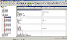
SEE Project Manager PLM is a product dedicated to the management of your electrical projects created with SEE software applications.
Designed for teamwork, SEE Project Manager PLM is perfectly adapted to small, medium and large companies. It centralizes and secures all your electrical data, integrating a “Vault” or “Safe” – type management in a native way.
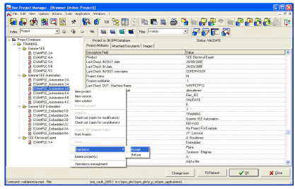 It allows searching, referencing, re-using of your electrical projects, as well as the traceability of operations realized in projects.
SEE Project Manager PLM organizes the entire electrical data flow that allows a better communication and coordination between different departments and work teams within your company (research department, Maintenance department, Purchasing department, etc.). SEE Project Manager PLM also shortens design deadlines.
SEE Project Manager PLM allows a product management in a collaborative context,
SEE Project Manager PLM ships with a default database, which will allow you to become operational instantaneously and will adapt very easily to your need, as they evolve.
According to the kind of the organization, you will be able to manage one (or several) databases containing your electrical projects.
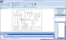
As for wiring diagrams SEE Electrical Expert is used to manage principle diagrams.
It manages:
• Link to SEE Electrical Equipement Definition to select equipment
• Connectivity between equipment
• Definition of net groups (to be use by Topology)
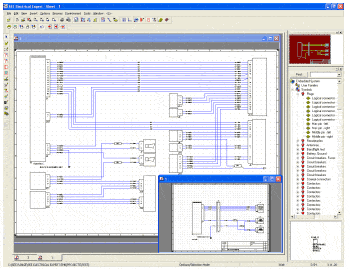
– Multiple sheets project management (off page referencing).
– Dedicated tools for signal insertion, symbols.
– Wires are cut automatically.
– Windows drag and drop, cut and paste and undo features, context menus, icon bars…
– Manual or automatic tagging of components.
– Real time management of cross-references (Multiple pages).
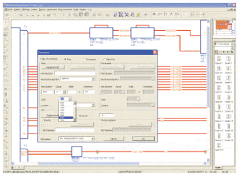
– Automatic connector insertion.
– Part number selection.
– Automatic numbering of connector pins according to part number.
– Management of all type of pins (contact, socket…).
– Real-time control (pin duplication, exceeding capacity, etc.).
– Pins management, swap pins, spares.
– Management of connector composition (backshells, pins and accessories).
– Management of inline connectors (Automatic pin numbering…).
– Real time management of signal networks. (nets)
– Management of cable and wire numbers, gauge, colour…
– Management of cable types (shielded, twisted, coax…).
– Selection of cable and wire part numbers.
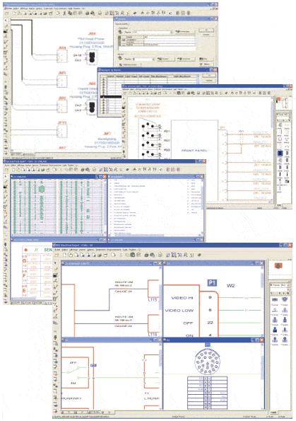
– Automatic lists generation of:
– Equipment lists,
– Wire lists,
– Cable lists,
– Manufacturing lists, etc…
Symbol libraries:
– Included symbol libraries of international standards such as ATA, BNAE, DOD-STD-863B…
Symbol editor:
– create, modify and organize symbol libraries.
Working methods:
Management of working methods according to standards.
Equipments, connectors, signals, wires and cable numbering.
Connectors, cables graphical representation.
Title blocks and page formats management.
Graphic formats
DXF/DWG, BMP, JPEG, TIFF, PCX, SVG,CGM…
Data exchange formats
XLS, DOC, HTML, XML …
[/col]
[/row]
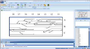
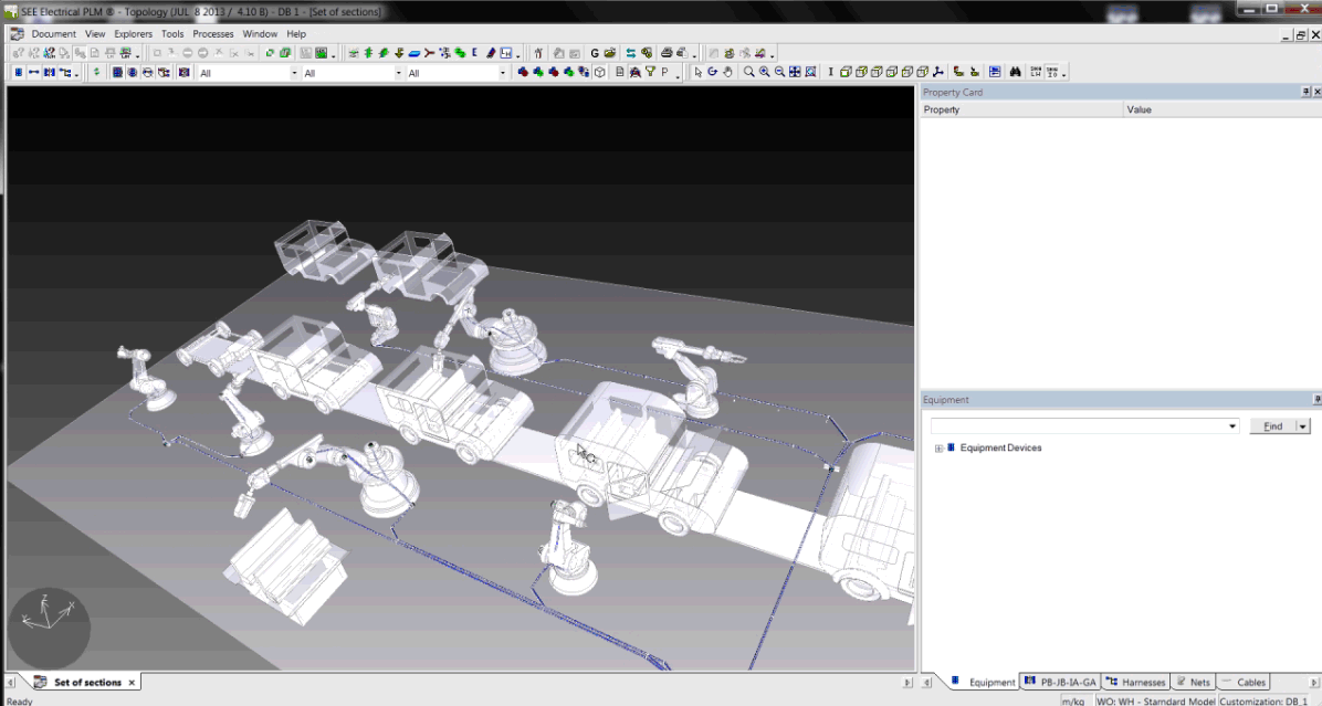
The Topology module allows the definition and modelling of wiring and harness systems as the result of Systems Integration process and 3D electrical installation.
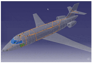
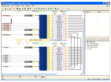
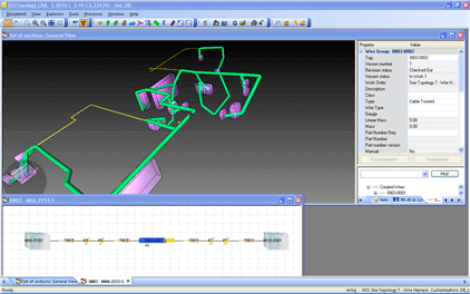
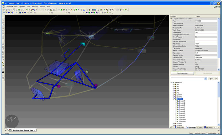
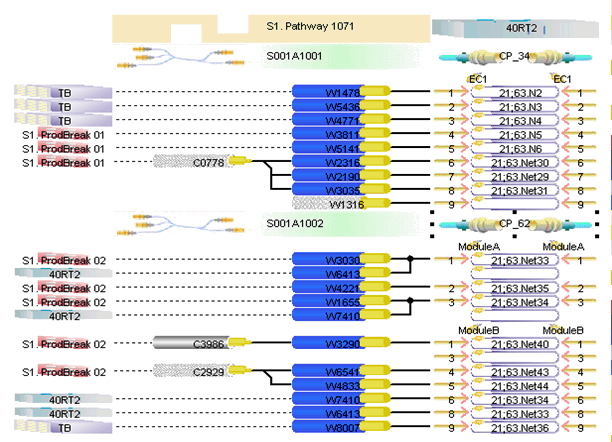
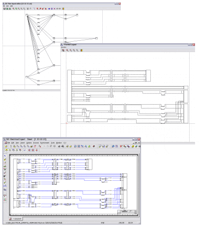
SEE Generative View allows to generate wiring diagram gathering information from the database, using logical harness data created by the Topology and Topology Viewer modules.
Drawings are then generated into SEE Electrical Expert.
This package is very efficient for troubleshooting or engineering review.
A physical harness results of the combination of:
•the wiring list of a harness (cables and connective devices, end-fitting)
•the geometry and mechanical accessories of a geometrical harness (branches with their geometry, protections, splice zones, accessories)
The physical harness calculation computes:
•The length of the cables, by routing them into the GH branches
•The branches diameter, due to cables and protections
•The harness characteristics such as mass, cost, gravity center, number of elements
•The bill of material of the harness
At release time, a PH part number is computed by automatic comparison with the other PH solutions
-Configuration Management
•Design several Systems / Installation / Harness alternatives
•Optimize re-use between alternatives
– Change Management
•Control all modifications applied to the database (security)
•Organize user tasks in Workflows (concurrent engineering)
•Keep track of all modifications (history tracking: who & when)
– Other standard PDM functionalities:
•Life-cycle management: keep track of design maturity
•Versioning: keep track of design evolutions
•Data Locking: Lock data during modification to avoid concurrent access
• By Product structure
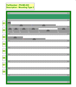
• By Integration Center ( Pannel/Rack)
• Equipment Center
• Disconnect brackets
• List of Equipment for 3D Installation design.
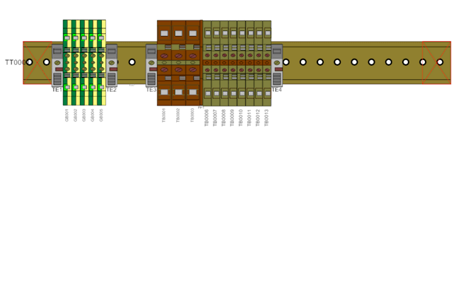
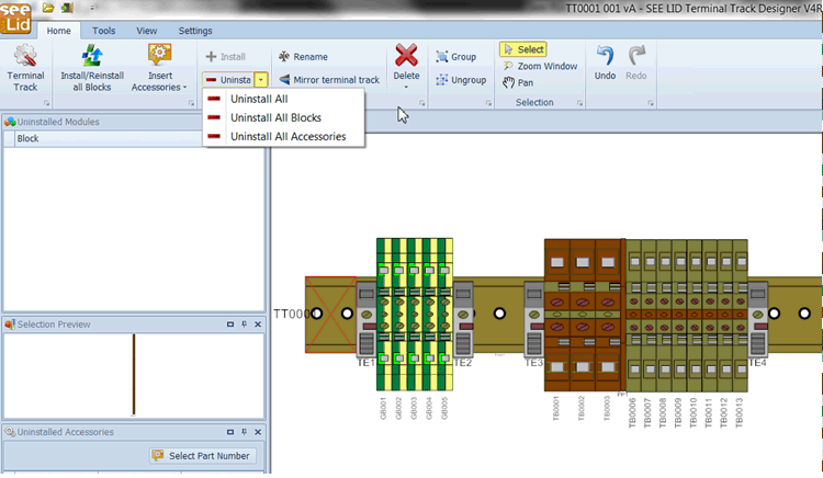
• Selection of the Terminal Track Part-Number
• Add accessories (Cover plate, Terminal stop, … )
• Desynchronize design of solutions from the design of the wire harnesses/wiring diagrams
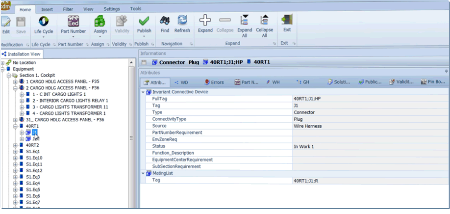
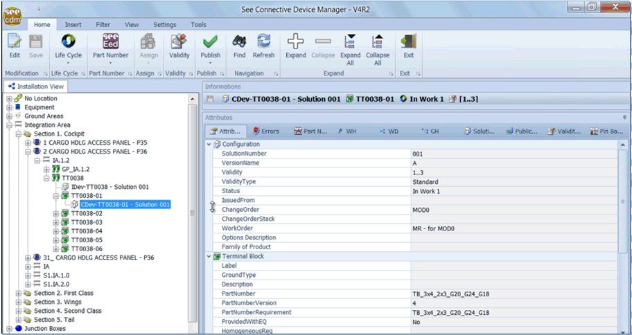
• Manage the position of the connective devices in the installation (location, installation device on which it is mounted)
• Provide pin booking tool
• Provide a Connective Devices Browser to help users of all applications to select connective devices
Harness documentation and flattening with SEE Electrical Jigboard
2 modes:
– “documentation”: create 2D drawing harness documentation – compare versions – insert wire grids and BOM (Bill of Materials) etc.
– “jigboard”: create the formboard on scale – compare versions – insert wire grids and BOM (Bill of Materials) – manage prededined formboard tables layout etc.
