SEE Electrical proposes numerous modules to better meet your needs for complete project execution. The most popular add-on is the SEE Web Catalogue, our online electrical equipments database.
This is a module for the efficient design of electrical cabinets in 3D.
This module allows you to professionally design control panels and cabinets in a 3D environment. The module requires a Grow or Scale configuration.
The application uses SEE Electrical’s apparatus catalogue to select the mounting plate and enclosure housing and insert rails and cable trays.
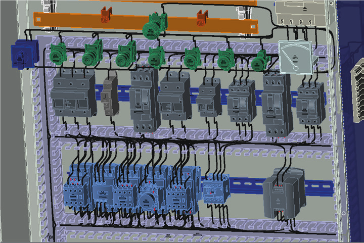
The components used in the electrical diagrams are available for use in the 3D design. The designer inserts 3D symbols on mounting rails, mounting plates or in free mode. A collision check and consistency check with the electrical schematic is carried out.
In addition, the module allows for the distribution of cables including the calculation of their length. The software also offers hole-punching drawings and export of hole-punch files to CNC tools.
This CAD module is used to draw electrical installations on building backgrounds (Available with the software at any level).
It is easy to use and includes libraries of electrical symbols as well as architectural elements.
It has the ability to create its own symbols and to insert text anywhere in the drawing.
Provides a simple way to implement your own design ideas.
Allows automatic rotation of symbols in relation to walls, easy copying and labelling.
The built-in editor allows building plans to be loaded. Available formats are DWG/DXF/DXB/PDF.
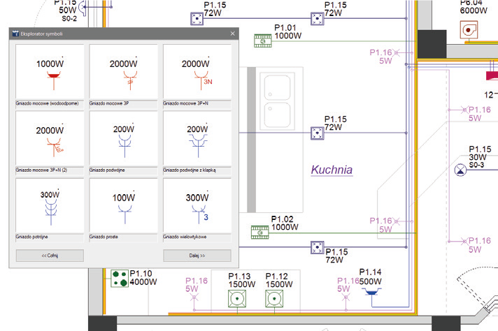
Walls, doors, windows and other objects can be easily inserted from the symbol database, allowing the user to easily create building plans.
Varied lists containing cabling and component information can be generated and exported to Excel sheets.
The application allows the automatic calculation of room areas as well as the insertion of cable trays and routing with the calculation of cable and wire lengths.
Single line diagrams are automatically generated from the installation plans created and circuits declared.
The module generates electrical diagrams from Excel sheets or Access databases. When similar schemas need to be created in different configurations, the automatic generation module provides considerable time savings. An Access database can be used by the sales department to create a quotation and then to automatically generate schemas.
The “Translation” module provides a database and translation tool. It is possible to translate an entire project into another language at the click of a mouse. If required, texts can be translated individually. In addition, the selection of the code page allows characters from different alphabets to be displayed in the schema at the same time, e.g. Cyrillic and Greek.
The translation database can be accessed while the text is being entered into the drawing, and a double-click adds the text to the database.
The easy to use online catalog offers electrical references and symbols. You can use this database directly in your drawing. Database includes related technical data. Your process of designing can be really fast and more efficient.